Nadia Korostyleva

Nadia Korostyleva

I enjoy working on a device end to end: CAD and fabrication, the electronics and firmware that drive it, the signal processing that makes sense of it, and the standards that define the process.

I am looking for medical device work where critical thinking, troubleshooting, optimization, and bringing multiple skills to the job are integral parts.

M.S. Biomedical Engineering, University of South Florida
Graduate Research Engineer, Acousto-Bioelectronics Lab
Tampa, Florida

Nadia Korostyleva in the lab, headphones round the neck and sunglasses pushed up into short dark hair, with a fume hood and printers behind.

Experience

  1. Graduate Research Engineer: Acousto-Bioelectronics Lab3D printing & CNC · Fabrication · Troubleshooting · Cleanroom · Modelling
  2. Engineering Intern: MiracleBots, LLC x University of South FloridaWireless & code · Electronics · Signal processing · Standards · 3D printing
  3. Hardware Tech Lead: IEEE Computer Society at USFEmbedded workshops · CAD & FDM printing · Curriculum
  4. Research Engineer: Gene & Regenerative Medicine LabIn vitro · In vivo · Analysis
  5. Junior Project Lead: University of South FloridaBiopotential sensing · BLE · Mobile app

Acousto-Bioelectronics Lab

Graduate Research Engineer

Acousto-Bioelectronics Lab — Dr. Albert Kim, University of South Florida
May 2025 to present — project lead on both programmes
MAP phototherapy patch · microfluidic brain slice perfusion chamber

Two device programmes, and the fabrication, electronics and modelling skills that both of them run on.

Additive and subtractive manufacturing

3D-printing, CNC, and laser cutting

I build most of my devices using additive or subtractive manufacturing. This covers: CAD modelling in SOLIDWORKS, 3D printing on FDM and SLA, CNC machining of the chamber bodies, Laser fabrication of smaller components, on both UV and CO₂ lasers, Metal sputtering

CAD model of a stent: a tubular diamond lattice of struts, shown isometrically.
Stent lattice.
A finished MAP device held between two gloved fingertips, a few millimetres across.
A finished device, a few millimetres across.
CAM software showing concentric toolpaths generated around two circular pockets, with the work origin and axes marked at the corner of the stock.
Toolpaths set up before cutting.
A machined aluminium ring off the mill, concentric tool marks across the face and two small slots cut into the bore.
A sample part off the mill.

End-to-end fabrication

From ideas to finished devices

I fabricate devices from the first idea through to a finished build, and then keep iterating on them. So far these include LED phototherapy patches, chemical sensors for the chamber, and microfluidic platforms.

I have built more than a hundred MAP devices across design iterations. Building that many is what made the design settle, because each batch showed up problems with yield and assembly that a single prototype would hide.

Three MAP devices illuminating wells of a six-well culture plate from beneath, each showing a three-by-three array of emitters through the plate base.
Finished devices delivering red light into a six-well plate.
Top: three microneedle electrodes side by side, labelled PANi/Au, Ag/AgCl and Pt, with a 2 mm scale bar. Bottom: a scanning electron micrograph of one needle with a 500 micrometre scale bar, and a magnified inset of its textured coating surface with a 20 micrometre scale bar.
Microneedle electrodes in three coatings, with the coating surface under SEM.
A fabricated microfluidic chamber layer held in a gloved hand, the channel network visible in the cast polymer.
A fabricated microfluidic layer.
Micrograph of the moulded microlens array, close-packed plano-convex lenses filling the frame with a scale bar at the lower edge.
The moulded microlens array.

Post-fabrication processes

Troubleshooting and validation

The device fabrication ran as a cycle: fix a problem, try to validate the working principle, find that the validation fails, and go back to fix it again.

Early MAP builds drew far more power than a wearable allows, so the early and fast work included evaluating current against voltage, the power that follows from them, and duty cycle.

Heat came next, because the LEDs were overheating the device against skin. Fans and heatsinking fixed that, and I validated the result at 37 °C. The redesign took 30 °C off the peak temperature and cut power consumption by two orders of magnitude.

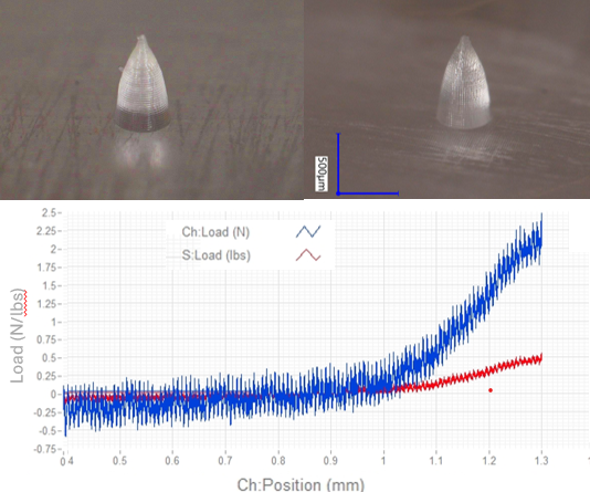
Mechanical validation was also a part of the work on my projects as I wanted to

The LED source array running, individual emitters visible through the lens optic against saturated red illumination.
The source array under drive, where the thermal and current measurements are taken.
Mechanical teatsing results: needle intact at the top left, slightly shortened at top right, load vs position graph at the bottom
Mechanical testing of the needles for future skin penetration on the Newton machine.

Semiconductor & Lithography training

Cleanroom

I am training to fabricate chips through the NSF Research Traineeship in Semiconductors and Microelectronics Technology, and run the cleanroom process behind the microfluidics device. Mask design in L-Edit.

Gowned in a full cleanroom suit, hood and overshoes, standing in the fabrication bay between benches of microscopes and process equipment.
Gowned up in the cleanroom at USF.

Modelling

COMSOL

Flow models decide the geometry before anything is cut — whether the velocity field over the tissue stays uniform across the chip.

COMSOL simulation showing velocity magnitude on a slice plane through the chip, with the tissue region outlined at the centre.
Chip flow test in COMSOL.

Publishing

First author at IEEE MEMS 2026

The work became a first-author conference paper and poster one month after I joined the lab: device concept, design and fabrication, irradiance characterisation, and the in vitro assays.

Holding the IEEE MEMS 2026 poster, titled Microneedle-Mediated Adaptive Phototherapy (MAP) Wound Patch with Microlenses.
The IEEE MEMS 2026 poster.

MirwacleBOts, LLC x USF

Engineering Intern

Semi-automated blood pressure regulation senior design project, University of South Florida, partnered with MiracleBots, LLC
August 2024 to May 2025 — team of three
ISO 14971 · ISO 13485 · ISO 81060-2 · IEC 60601-2-24

The three of us built a semi-automated blood pressure regulation system: a non-invasive cuff, a peristaltic pump that delivers nicardipine, and the software that connects them. It keeps a patient's pressure in range on its own, so a clinician does not have to reset the dose by hand every few minutes.

Wireless communication and code

Two boards, one client, and user interface between them

The system holds a patient's blood pressure where the clinician wants it, using the prescribed medication, without anyone adjusting the rate by hand. That helps in an emergency, and for patients who need fluids whenever their pressure drops, or medication to bring a high pressure down.

The cuff and the pump never talk to each other directly. Each one is an ESP32 running a BLE server, and a single Python application connects to both. It reads the pressure from the cuff, works out a dose, and sends the rate, duration and drug type to the pump.

Everything passes through that application, so a cuff reading cannot reach the pump on its own. The interface shows the measured pressure, the heart rate and a suggested rate, and nothing is delivered until the clinician confirms it.

I wrote the software across Python, C++ and MATLAB: the signal processing, the wireless communication, the safety checks in the code, and the hardware programming. The dosing model learns how an individual patient responds to a dose instead of following a fixed schedule.

System flow titled BLE and GUI: the BP cuff sends its pressure value over Bluetooth Low Energy to the user PC, where the GUI processes the values, computes a dose and duration from the systolic pressure, and asks the clinician to confirm; on confirmation a second BLE link sends the rate to the IV pump, which administers the dose.
The loop end to end — cuff to PC over BLE, a dose the clinician confirms, then PC to pump.
ESP32 firmware in an editor: the BLE service and characteristic UUIDs defined as constants, state flags for connection and measurement, systolic and diastolic thresholds, and a BLEServerCallbacks class with onConnect and onDisconnect setting the connected flag.
The BLE server on the ESP32 — service and characteristic UUIDs, and the connect and disconnect callbacks.
The clinician application: authorization options for logging in or creating an account, then the measured blood pressure of 107.3 over 66.2 and heart rate of 56, a suggested nicardipine dose of 6 mg per hour, an editable rate field, and an Administer button.
The clinician application. The suggested dose is editable, and nothing is delivered without an explicit Administer.

Electronic components

Building the pump and the cuff

Each enclosure carries its own supply and control. A 24 V wall supply is bucked down to 5 V for the logic; an ESP32 Wroom holds the BLE link and drives a motor driver over RS485, which turns the peristaltic pump head. A micro-servo handles the medication switch.

The cuff side is the same idea with different actuators: 7.5 V bucked to 5 V, an ESP32 driving an H-bridge that runs a diaphragm air pump and a solenoid valve, and a pressure sensor tapped into the cuff line.Those two inflate the cuff and then let the air out at a controlled rate, since the measurement depends on how fast the pressure falls.

Annotated wiring diagram of the pump module: a 24 volt wall supply feeding a buck converter down to 5 volts, an ESP32 Wroom and a MODBUS RS485 chip on a prototyping board, a motor driver running the peristaltic pump, and a micro-servo.
Pump module — 24 V in, buck to 5 V, ESP32 driving the motor over RS485.
Annotated wiring diagram of the cuff module: a 7.5 volt wall mount feeding a buck converter to 5 volts, an ESP32 Wroom driving an H-bridge that runs an air pump and a solenoid valve, with a pressure sensor tapped into the cuff line.
Cuff module — air pump and solenoid valve off an H-bridge, pressure sensor on the cuff line.
Inside the pump enclosure: a microcontroller board on a standoff rail above a bank of colour-coded terminal blocks, with looms running down to the components below.
The pump enclosure, wired.
Inside the printed cuff enclosure: a motor driver board and an ESP32 on a prototyping board wired to a solenoid valve and a diaphragm air pump seated in printed brackets.
The cuff enclosure — driver, ESP32, solenoid valve and air pump.

Signal processing

Recovering a pressure from a deflation curve

We measure pressure with the cuff indirectly: it inflates, the pressure falls slowly, and every heartbeat shows up as a small oscillation riding on that falling curve. I wrote the signal processing that separates those oscillations out with a bandpass filter and reads the systolic and diastolic values from the size of the pulses.

The filtering and the peak detection run on the signal as it arrives rather than on a saved recording, because the next dose depends on the reading that just came in.

Measured cuff pressure decaying from about 155 to 50 mmHg over roughly nine seconds, with small oscillometric pulses visible on the curve.
Reading from the cuff on a real person, decaying from about 155 to 50 mmHg with visible oscillometric pulses.
The extracted oscillometric pulse envelope with detected peaks marked, and horizontal thresholds for the systolic and diastolic ratios.
Filtereded signal with cutoffs at the derived thresholds marking systolic and diastolic pressure.

Standards

Following ISO protocols to fix and validate

Four standards shaped the design, and each one changed something in the result.

ISO 14971
While working on our devices, we ran risk assessment and management that defined our choices in the design, even if this meant making the device more complicated.
ISO 13485
During the device development, we kept a design history and controlled every revision, so any requirement could be traced to the part of the device that satisfies it.
ISO 81060-2
We validated the cuff against this standard, which set how accurate the measurement had to be and the conditions it had to hold that accuracy under.
IEC 60601-2-24
We built the pump to this standard, which set the delivery accuracy, how the pump behaves when a line blocks, and when it has to stop delivering.

CAD & 3D-printing

Printed housings for both devices

We printed both enclosures ourselves, giving every component its own seat inside so nothing moves around and the clearances that medical electrical safety needs stay intact. We also added vents for cooling, a hole for the power inlet, routing for the tubing that connects to the IV line and the switch between lines, as well as the fixtures that clamp the system to a standard IV pole. The motor and the commercial pump head were seated outside the box, with their electrical connections inside.

We designed the first pump head ourselves, modelling the roller spacing and the tubing path that set how much fluid moves per turn, and then moved to a commercial head.

The pump drawn as two parts side by side: the housing with its tubing channel cut away, and the four-roller head on its shaft with the tubing wrapped around it.
Initial design idea.
The system on the pole seen from further back: an IV bag hung above the printed monitoring enclosure, the pump module below it, and lines running down to the bench.
The cuff fitted for a measurement.
The non-invasive cuff fitted on an upper arm, tubing running to the pole-mounted monitoring enclosure.
Both printed enclosures mounted on a standard IV pole.

IEEE Computer Society

IEEE Computer Society at USF

Hardware Tech Lead
August 2025 to present
200+ attendees, 100+ devices built

Teaching embedded hardware by building devices that only work if you understand why.

Morse-code IoT device workshop

LED and photosensor data transmission

I built this session around two Particle Argon boards that talk over a beam of visible light. The sender drives an LED from a digital pin, and the receiver that reads photocurrent from the photosensor as analog input and wires a second LED to follow the increases and decreses in the input.

Working in pairs, the student were tasked with building both components step-by-step, program their devices and troubleshoot to make their devices work and be able to replicate them in the future. The students then encoded and transmitted Morse code at the sender and decoded information on the receiver end, testing it with the room lights off.

Walking a full room through the sender assembly, with the breadboard wiring diagram projected on screen.
Walking the room through the sender assembly.

Mobile Phone IoT Workshop

Talking from microphone to dynamic over WiFi

The second workshop moves to audio: two ESP32 boards carrying sound between them over I²S, with a MEMS microphone on one end and a Class-D amplifier driving a speaker on the other.

Students built both ends, programmed the boards, and worked through the I²S interface: bit clock, word select, and how a sample stream is framed. By the end each pair could talk into their microphone and hear it come out of the speaker across the room.

Wiring a speaker into an ESP32 breadboard build while two attendees look on.
Debugging a build mid-session.

Solidworksa and FDM printing

Building Minecraft cat CAD

I built this session around a Minecraft cat model in SOLIDWORKS. The build goes through the basic CAD functions one at a time — sketching, extrusion, and the buttons students keep coming back to. Working along with me, the students were tasked with modelling the cat step-by-step, so they could repeat the process on their own parts later. We then went through the slicer software, SLA and FDM printing and what each is good for, and the resources available to them on campus and online.

Teaching a parametric SOLIDWORKS sketch, dimensioning an extruded profile on the projected screen.
Presenting the 3D printing workflow — modelling, export, slicing, and choosing a printer.
Dimensioned SOLIDWORKS drawing of a glasses nose pad in millimetres: front, side and bottom views with a shaded isometric.
A worked example for the CAD track — a glasses nose pad, fully dimensioned.
Three painted Minecraft cat models, printed in one piece and hand painted in white, orange and black.
Printed Minecraft cats, hand painted — a build students take home.

Knowledge Transfer

Built backwards from a device that has to work

Similarly to how I work in my job, I design and run hardware workshops in a way where students have to build a real device/part from scratch and can then take it home or continue using this knowledge to build things themselves.

Sessions run in pairs so people can network with each other and acquire new connection, which is especially important for new students on campus. We have had over 200 attendees so far, and more than 100 devices built.

A packed lecture room seen from the back: every seat taken, laptops open along the benches with kit boxes beside them, and a slide projected at the front.
A full room mid-workshop — every seat, every laptop, a kit each.

Gene & Regenerative Medicine Lab

Research Engineer

Dr. Anna Bulysheva
Contributed to two publications
IACUC certified

Gene electrotransfer experiments in mammalian cell lines and rodent models, and the analysis behind the published figures. For six months I ran the lab on my own: managing the space, quoting supplies, maintaining the equipment and training new members.

In vitro

Cell work at the bench

I ran the in vitro side of the lab's gene electrotransfer work: maintaining the mammalian and human cell lines, designing and running the treatment conditions, and preparing the samples the downstream analysis depended on, including fluorescent and antibody staining. I also developed and optimised the protocols across the lines I worked with.

Phase contrast micrograph down the eyepiece: spindle-shaped adherent cells spread across the field at moderate confluence.
Cells checked under phase contrast before a run.

In vivo

Animal studies, IACUC certified

The in vivo work took the same gene electrotransfer into rodent models. I prepared the protocols, performed the surgery and delivered the therapy that followed it, drew the blood samples, then extracted and prepared the histology samples and imaged them on luminescent settings. I am certified through USF IACUC in rodent methodology and aseptic surgical technique.

This fed two sets of published results: localised in vivo electro gene therapy for reprogramming skeletal muscle into a protein factory, and pulse protocols that trade delivery efficiency against muscle contraction.

AALAS Learning Library certificate recording completion of the USF IACUC course in rodent aseptic surgical technique, dated June 2024.
USF IACUC — rodent aseptic surgical technique.
A page of squared lab notebook headed Rat 1, with a hand-drawn dorsal view of the animal and four numbered treatment sites marked along the flank and hindquarter.
Study notes — treatment sites numbered per animal before a session.

Data Processing

Statistical analysis and figure design

I ran the statistical analysis in Prism and SPSS, quantified expression from the images, and made the figures. I documented the experiments, learned how to write a journal paper, answered the reviewer feedback and submitted it. The work also went into two ASGCT conference abstracts and posters.

Bioluminescent flux in photons per second on a log axis against time in days, out past 300 days, comparing four electroporation pulse protocols with an injection-only control. The 90 volt 150 millisecond condition holds two to three orders of magnitude above the rest throughout.
Expression tracked out past 300 days by pulse protocol, from our Applied Sciences paper.

University of South Florida

Junior Project Lead

Wireless EOG drowsiness monitor junior design project, organized by University of South Florida
April to May 2024
Top three of fifteen teams, 2024 Florida Medical Manufacturing Consortium

BA wearable that reads eye movement through electrodes on the face, counts blinks, and flags drowsiness. We built it for truck drivers, where fatigue is behind a share of fatal crashes and blink rate is a validated marker of it.

EOG Signal

Leveraging ocular muscle biopotential

Electrooculography reads the standing potential between the cornea and the retina, about 6 mV, so every eye movement and blink shows up directly in the signal. We put the inverting input above the eyebrow, the non-inverting input beside the outer eye, and the reference on the jaw.

The acquisition circuit is a passive bandpass filter with cutoffs at 0.72 and 15.9 Hz feeding an instrumentation amplifier, with the output offset between 0 and 5 V so the Arduino could read it. Two 9 V batteries give the split supply, and a buzzer and indicator LED sit on the board for the alert.

Diagram of electrode placement on a face: the inverting input above the eyebrow, the non-inverting input beside the outer eye, and the reference on the jaw.
Electrode placement — two inputs across the eye, reference on the jaw.
The wearable in use: electrodes taped above and beside one eye, their leads running down to a printed yellow enclosure clipped at the shoulder.
The wearable in use, enclosure clipped at the shoulder.
Circuit layout: an Arduino Uno and a breadboarded instrumentation amplifier stage with gain-setting resistors, a buzzer and an indicator LED, powered from two nine volt batteries.
The acquisition circuit — instrumentation amplifier stage, split supply from two 9 V batteries.

Communication and Code

Bluetooth data transfer to mobile app

The Arduino code detects the peaks in the EOG and PPG traces and derives the blink and pulse frequencies from them, with a fourth-order Butterworth filter smoothing the signal before detection. The device sends the result over Bluetooth to a phone app I built in MIT App Inventor, which shows the blink events as they arrive and the current awake or drowsy state. We added PPG so the drowsiness reading has a second signal behind it rather than resting on blink count alone.

A sample trace recorded from the wearable: amplitude in ADC units against time in milliseconds, showing four slow rising ramps with sharp falls over two and a half seconds.
A sample trace captured from the device.
The companion app: a bar trace of blink events over time, a state readout showing awake, and Bluetooth connect and device selection controls along the bottom.
The companion app — blink events, the awake or drowsy state, and the BLE connection controls.

Outcome

Top three of fifteen

We presented at the 2024 Florida Medical Manufacturing Consortium, where the project was selected as one of the top three of fifteen teams in the cohort.

Six of us standing beside the welcome board at the Florida Medical Device Symposium in St. Petersburg, all wearing lanyards.
At the Florida Medical Device Symposium, May 2024.

Publications

What I work with

Fabrication

Cleanroom processing and photolithography, mask design in L-Edit, microneedle and microlens array fabrication, CNC machining, FDM and SLA 3D printing.

Electronics and firmware

Embedded development on ESP32 and Particle Argon, I²S and analog sensor interfacing, BLE and Wi-Fi links, breadboard prototyping and hardware debug.

Software and analysis

Python, C++, MATLAB, SPSS, machine learning for physiological response modelling.

Wet lab

In vitro work with mammalian and human cell lines; in vivo rodent studies including surgery and imaging, IACUC certified.

Standards

ISO 14971 risk management, ISO 13485 quality systems, ISO 81060-2, IEC 60601-2-24.

Design and simulation

SOLIDWORKS, Autodesk Fusion, COMSOL Multiphysics for thermal and optical modelling.

Awards and programs

Three of us standing side by side, each holding a framed certificate.
With other awarded members, April 2025.